PIC-USB-4550
| Price | 12.95 EUR |
|---|---|
| 10 - 49 pcs | 11.66 EUR |
| 50 - 10000 pcs | 10.36 EUR |
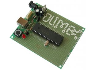
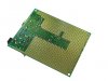
This is a handy prototype board for developing USB applications with a PIC18F4550 microcontroller. What's great all about it is that if you want to only load code into it, i.e. to program it, you can do this without any additional programmer. Microchip provides free USB solutions for their microcontrollers which are available for you to use off the shelf: USB HID Class firmware you can build a mouse or other Himan Interface Device for Windows, USB CDC Communication class device, USB Mass Storage firmware - add your own USB disk drives to your computer, USB-to-RS232 driver. The plenty of prototype space allows you easy to add on sensors, relays and other peripheral devices to interface to USB. The board can take power from USB or from External supply with small jumper selection. RESET button, User button and LED are on-board.
FEATURES
- ICSP/ICD connector for programming with PIC-MCP, PIC-MCP-USB, PIC-PG1,PIC-PG2, PIC-PG3 or PIC-PG4 and programming and debugging with PIC-ICD2, PIC-ICD2-POCKET, PIC-ICD2-TINY
- USB 2.0 type B connector allow board to be interfaced to PC host.
- PIC18F4550-I/P on DIL40 socket
- Quartz crystal 20Mhz
- LED connected to RD3 through jumper
- User Button connected to RB4
- Reset button
- Power plug-in jack with diode bridge can be powered with AC or DC power supply
- 5V voltage regulator
- Extension slot on every uC pin
- Gird 100 mils
- GND bus
- Vcc bus
- Four mounting holes 3,3 mm (0,13")
- FR-4, 1.5 mm (0,062"), green soldermask, white silkscreen component print
- Dimensions 100x80 mm (3,9x3,15")
DOCUMENTS
HARDWARE
SOFTWARE
- Blink LED demo code
- Button read demo code
- USB bootloader (C source and HEX)
FAQ
- How to program the board via the USB?
- Power the board - apply 9V DC voltage to the power jack. Connect USB cable between the board and the personal computer. Put the board in bootloader mode - press and hold button BUT (big button) then press briefly RST button and finally release button BUT. The LED should turn off and a new device should be visible in your computer (usually called "Microchip Custom USB Device"). Then download the "MCHPFSUSB v2.2 USB Framework" from Microchip - it contains the PDFSUSB tool in folder "\USB Tools\Pdfsusb" - start the software and you are good to upload your hex to the board!